MLCC vs. Film Capacitors: Key Differences for Your Design
Jun 24, 2025
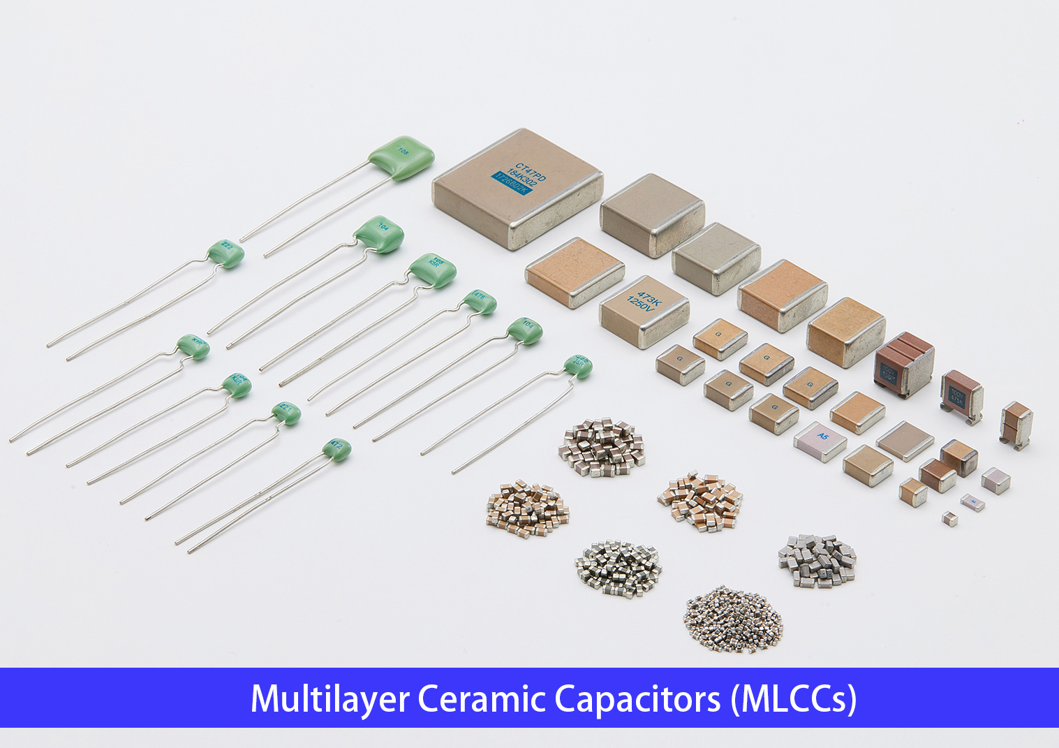
In the world of electronic circuits, capacitors are indispensable fundamental components. When it comes to design selection, the debate of ceramic capacitor vs film capacitor is one of the most common among engineers. Among the many types available, Multilayer Ceramic Capacitors (MLCCs) and Film Capacitors stand out for their unique characteristics and widespread use across different fields.
Before diving into the comparison, a common question arises: MLCC vs ceramic capacitor—what is the difference? Essentially, an MLCC capacitor is the most widely used type of ceramic capacitor. Furthermore, when comparing a multilayer ceramic capacitor vs single layer, MLCCs offer significantly higher capacitance within a compact footprint by stacking alternating layers of ceramic and metal.
The most obvious difference is their physical appearance. But how do they truly differ in circuit performance? This article comprehensively compares the film capacitor vs ceramic capacitor across dimensions, materials, performance, and applications to help you make optimal design choices.
1. Material Composition
Ceramic (MLCCs): Use ceramic materials like Barium Titanate (BaTiO₃) as the dielectric. These ceramics offer high dielectric constants, enabling relatively large capacitance values within small physical volumes.
Film Capacitors: Utilize plastic films such as Biaxially-Oriented Polypropylene (BOPP) or Polyimide (PI) as the dielectric. Electrodes are formed on the film surface through a metallization process.
2. Size & Form Factor
MLCCs: Hold a significant advantage in miniaturization. Common package sizes range from tiny 01005 up to 2220 and beyond. This makes them ideal for high-density PCBs in compact consumer electronics.
Film Capacitors: Due to their manufacturing process, they are generally larger. Achieving the micro sizes of MLCCs is challenging. However, size is less critical in applications where high voltage and reliability outweigh miniaturization.
3. Application Areas: Film Capacitors vs Ceramic
MLCCs: Excel in applications requiring good high-frequency characteristics. They are commonly found in RF circuits, high-speed digital circuits, and power supply filtering sections.
Film Capacitors: Shine in high-voltage and high-power scenarios due to their inherent self-healing capability. Typical applications include inverters for New Energy Vehicles (NEVs), reactive power compensation, and high-fidelity audio equipment.
4. Performance Advantages & Disadvantages
MLCCs (Ceramic Capacitors):
Advantages: Very small size, low cost, suitability for mass production, good temperature stability (for certain types like X7R, C0G/NP0), such as the Torch CC41 Series SMD Multilayer Ceramic Chip Capacitor.
Disadvantages: Larger capacitance values require significantly larger sizes. Prone to thermal failure under high ripple currents. Susceptible to mechanical stress fractures ("micro-cracks"). Piezoelectric effects can cause audible noise.
Film Capacitors:
Advantages: High precision, excellent long-term stability, very low losses (high Q), ability to withstand high transient voltages.
Disadvantages: More complex manufacturing process leading to higher costs. Difficult to achieve very small SMDs.
How to Choose? Key Considerations for Designers
• Frequency: For high-frequency circuits, prioritize ceramic MLCCs. For lower frequencies, consider film.
• Precision & Stability: Where high precision is critical, film capacitors are superior. If cost outweighs extreme precision, MLCCs offer better value.
• Voltage: In high-voltage power environments, film capacitors are the safer bet.
• Space Constraints: In miniaturized designs, the small size of MLCCs is paramount.
Conclusion
The debate of ceramic vs film capacitor ultimately depends on your specific application. They exhibit significant differences in material, size, and performance. As the global plastic film capacitors market continues to grow—driven by green energy and automotive electronics—and MLCCs continue to dominate compact devices, making the optimal choice ensures circuit performance is maximized. Evaluate your frequency range, voltage levels, precision needs, and physical space constraints to weigh the trade-offs effectively.
Read More


 IPv6 network supported


