
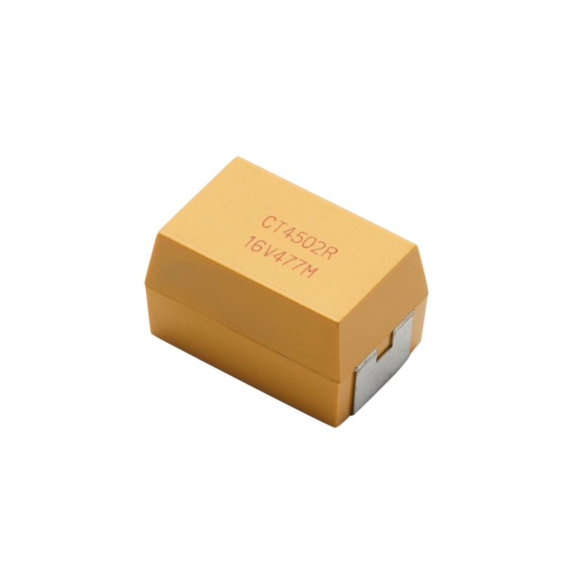
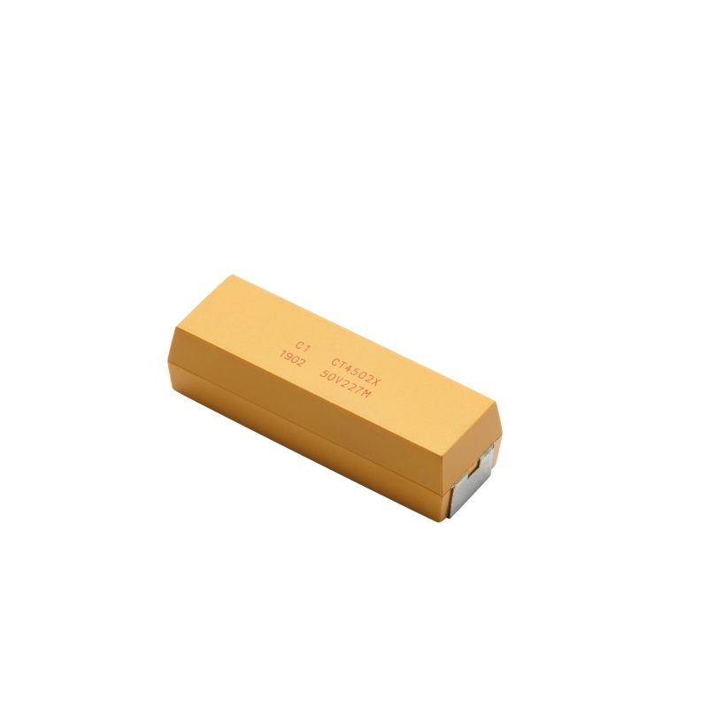
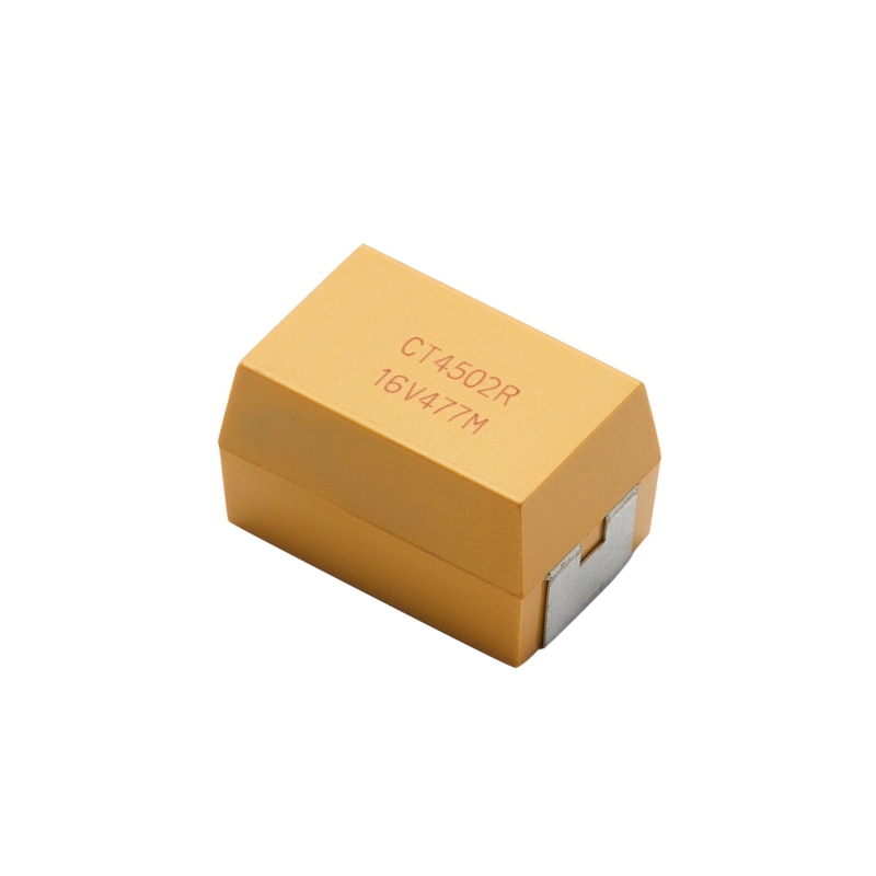
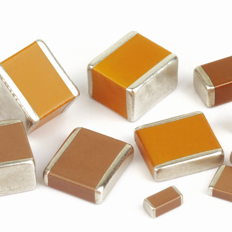
Capacitance ranging from 0.1 F to 3300uF
Voltage ratings of 6V-500V
Operating temperature range:
X7R: -55℃~125℃
X5R: -55℃~85℃
Epoxy molded, high physical strength
Tin/Lead solder plated (4% Pb minimum)
100% temperature cycling
100% accelerated steady state aging
Ordering Information
|
CT4502 |
T |
X5R |
25V |
477 |
K |
T |
A |
|
Series |
Case size |
Dielectric |
Rated voltage |
Capacitance(pF) |
Capacitance tolerance |
Packaging |
Test Level for COTS |
|
CT4502 |
E N M T L |
X7R X7S X5R |
6V 10V 16V 25V 35V 50V 100V 200V 500V 1KV 2KV |
First two digits represent significant figures. Third digit specifies number of zeros. Example: 477=470000000pF =470F |
K=±10% M=±20% |
T=Bulk |
A B C |
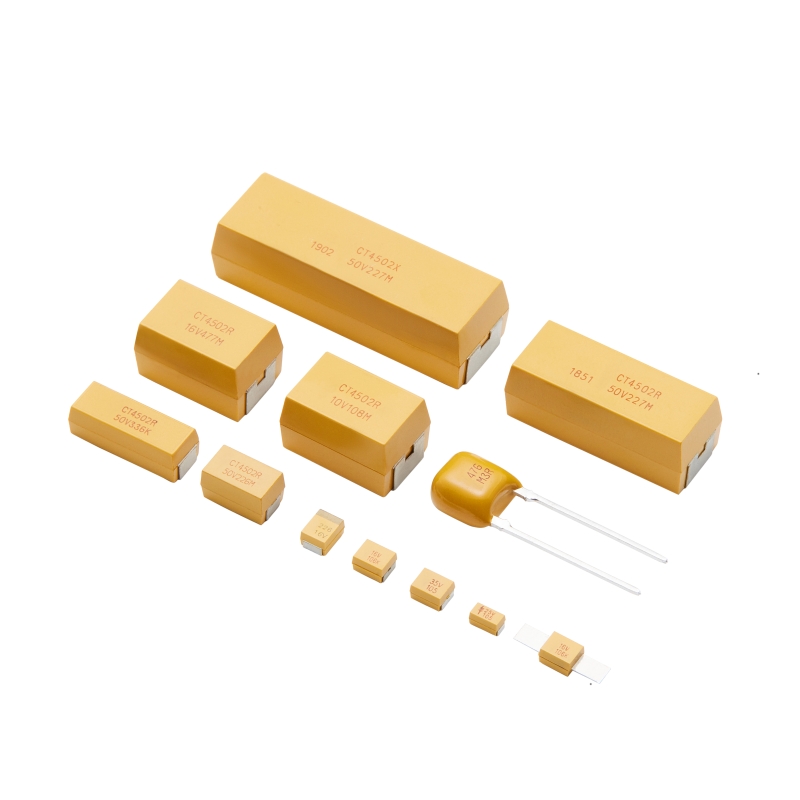
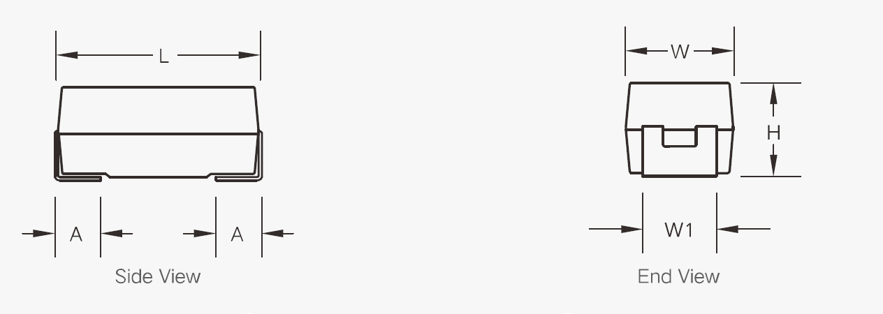
Dimensions
|
|
|
|
|
|
|
|
|
|
Unit:mm |
|
E |
N |
M |
T |
L |
|||||
|
L |
7.30±0.20 |
L |
12.7±0.50 |
L |
12.7±0.50 |
L |
20.50±0.50 |
L |
30.50±0.50 |
|
W |
4.30±0.20 |
W |
4.70±0.20 |
W |
8.40±0.20 |
W |
8.40±0.20 |
W |
9.90±0.20 |
|
H |
4.10±0.30 |
H |
4.10±0.25 |
H |
7.60±0.25 |
H |
7.60±0.25 |
H |
8.50±0.25 |
|
W1 |
2,40±0.20 |
W1 |
3.00±0.20 |
W1 |
5.20±0.20 |
W1 |
5.20±0.20 |
W1 |
6.60±0.20 |
|
A |
1.25±0.30 |
A |
1.50±0.30 |
A |
2.00±0.30 |
A |
2.00±0.30 |
A |
3.00±0.30 |
Electrical Characteristics
|
Item |
Specification Limits |
Measuring Conditions |
||
|
Operating Temperature Range |
X7R |
-55℃ to +125℃ |
— |
|
|
X5R |
-55℃ to +85℃ |
|||
|
Capacitance |
Within specified tolerance |
— |
||
|
Dissipation Factor |
X7R |
UR≤50V tgδ≤3.5% 50V<UR≤500V tgδ≤2.5% |
CR≤10μF 1.0kHz±10% 1Vrms±0.2V 10μF<CR<470μF 120Hz±10% 0.50Vrms±0.2V 470μF≤CR<2000μF 50Hz±10% 0.50Vrms±0.1V 2000μF≤CR<4700μF 25Hz±10% 0.25Vrms±0.1V |
|
|
X5R |
UR≤50V tgδ≤10% 50V<UR≤100V tgδ≤3.5%; 100V<UR≤500V tgδ≤2.5% |
|||
|
Insulation Resistance |
100MΩ·μF |
Rated voltage shall be applied for 2 minutes, charging and discharging current shall be 50mA or less. |
||
|
Dielectric Strength |
No breakdown or visual defects |
Rated voltage shall be applied within following conditions for 5 seconds: UR<500V 2.5UR UR=500V 1.5UR Charging and discharging current shall be 50mA or less. |
||
|
Temperature Characteristics |
±15% |
Capacitance change with reference to +25℃ |
||
Capacitance ranging from 0.1 F to 3300uF Voltage ratings of 6V-500V Operating temperature range: X7R: -55℃~125℃ X5R: -55℃~85℃ Epoxy molded, high physical strength Tin/Lead solder plated (4% Pb minimum) 100% temperature cycling 100% accelerated steady state aging
Read More
Lead-free terminations, RoHS and Reach Compliant
Read More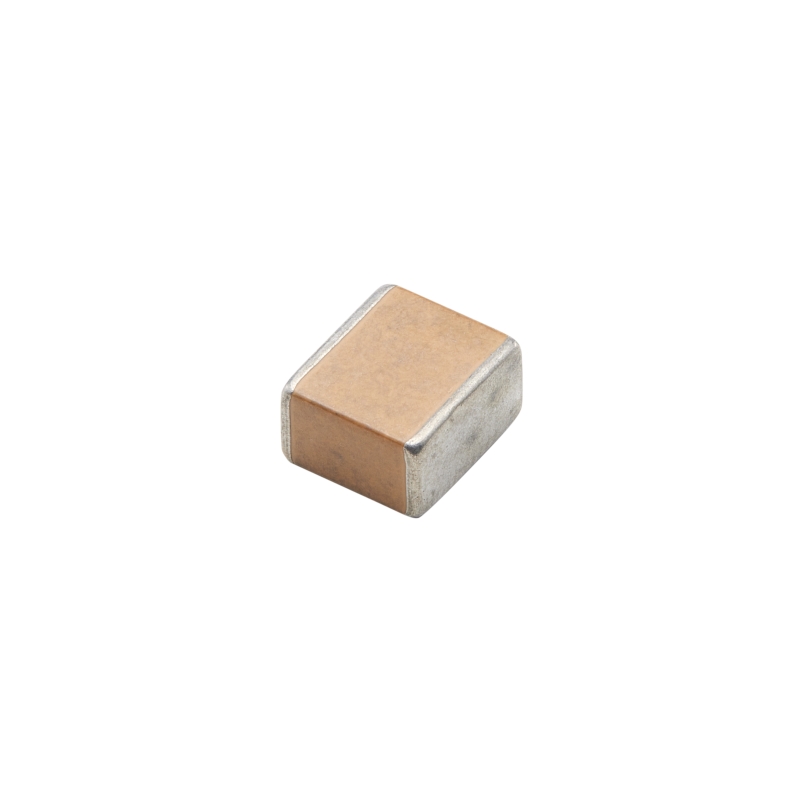
Lead-free terminations, RoHS and Reach Compliant
Read More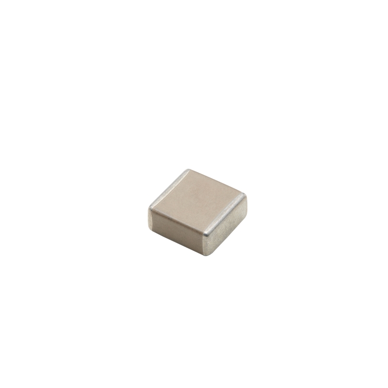
Lead-free terminations, RoHS and Reach Compliant
Read More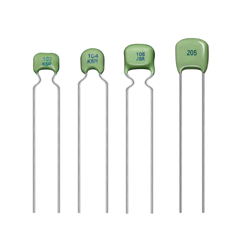
The Torch CC4 Series C0G Capacitor is a premium radial lead type capacitor engineered for applications requiring high stability and low loss. Utilizing Class I dielectric materials, this C0G ceramic capacitor delivers exceptional temperature compensation (-55℃ to +125℃) with virtually no capacitance variation over time or voltage. Available in standard and custom radial lead configurations, it is the ideal choice for industrial control, medical care, and precision electronic circuits.
Read More
Lead-free terminations, RoHS and Reach Compliant
Read More


 IPv6 network supported


